EPS: Electrical Power Supply
Electrical Power Supply (EPS)
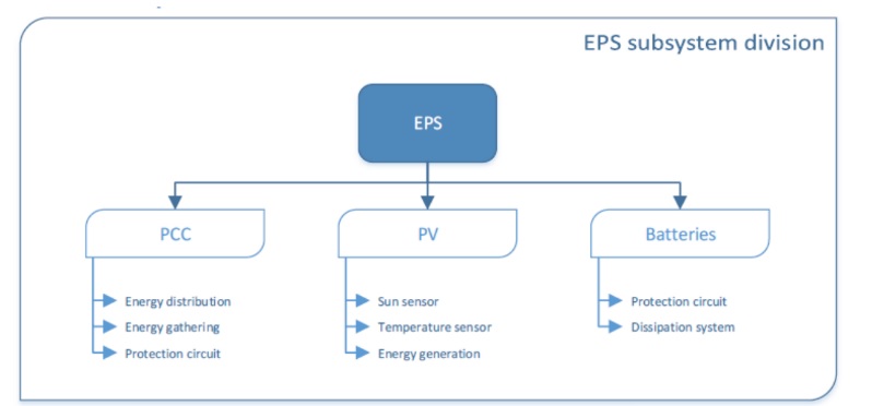
The Electrical Power Supply, or EPS of the CubeSat is composed by three modules which are the PCC (Power Control Circuit), the PV (photovoltaic panel) and the BAT (Battery). The role of the EPS is to generate, store and distribute the electricity produced by the solar panels.
Subsystems of EPS
PCC is responsible for the voltage regulation, the modules protection and the energy distribution. In others words, it has to manage the energy through the ECE3Sat. It communicates with the OBC, thanks to a microcontroller.
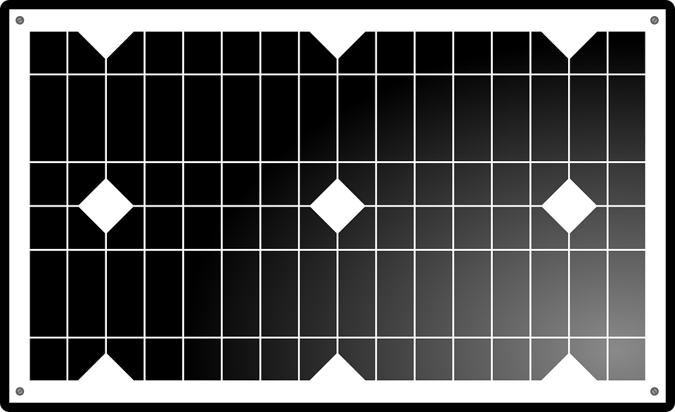
The PV has to generate the electricity using the sunlight and the photovoltaic effect. This will be possible thanks to five solar panels, on each side of the CubeSat.
The BAT module has to store this energy to enable its using at any time.
State Of The Art
The goal of the state of the art is to establish an inventory of the existing technologies and to see their underlying potential of their utilization in the project.
PV
The solar cells generate electricity by absorbing sunlight thanks to the photovoltaic effect.
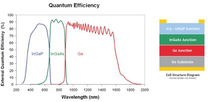
In space at Low Earth Orbit, the sunlight is not filtered by the atmosphere. The efficiency of a solar panel depends of the wavelength of the photons that it can absorb. Therefore, in a space context with a larger wavelength of photons available than at Earth, the technology used for the solar cells has to be able to absorb the maximum amount of photons. More, since the area available of the solar panel is strongly limited on the CubeSat (each side size 100 cm², and has to integrate solar cells but also sensors and wires). The triple junction technology solar cells have a layer well adapt to a large wavelength area with an absorption wavelength from 300 nm to 1700 nm. This option but also other types of technology have been study in the State of the Art document.
BAT
The energy produced by PV panels has to be stored partially to deal with the eclipse period in which there is no more sunlight, and so no more electricity production.
Batteries are generally the preferred method of energy storage for CubeSats. There are several factors to consider when choosing the dimensions and technology.
The nominal voltage has to be line with the buses voltage required by the modules supplied by the battery.
The energy density determines the size of the battery compared to the needed energy
The maximum discharging current limits the maximum number of modules running at the same time. This also limits the maximum consumption of any single module.
The self-discharge will affect the battery capacity, so it must be taken into account when deciding the total capacity.
The charging time of the battery minus the oversize part cannot be longer than the sunshine time, or else it will be a lack of electricity during the eclipse.
The thermal charging and discharging range are linked to the spacial conditions, and must be line with the thermal regulation modules to provide optimal or minimal operating conditions
The maximum number of cycles depends on the length of the space mission. As the capacity of the battery diminishes over time, one can choose to over-size the battery or to choose a type which has a higher number of maximum cycles.
Many kinds of 1U batteries already exist. The power stored in each of these batteries is about 10 to 30 Wh.
The ECE3SAT team considered different type of battery technology, including chemical batteries. The maximum energy density and watt-hour per kilogram rate with a correct price are the Lithium batteries (in the chemical battery technology). This technology is usually the one which is used in CubeSats.
The lithium batteries (Li) can be divided in two categories. Lithium Polymer or Li-Po, and Lithium Ion or Li-Ion. These two categories have both advantages and disadvantages comparing with the other.
Lithium Polymer
- Strengths:
- Can have different tiny forms
- Low weight
- Safest batteries
- Weaknesses:
- Less Energy saving than Li-Ion batteries
- More expansive
- Regulated charge
Lithium Ion
- Strengths:
- Can have different tiny forms
- Low weight
- Highest power saving
- Weaknesses:
- Shortest life cycle than Lithium Polymer batteries
- Can cause bypass
PCC
When the electricity has been generated by the solar panels. It has to be manage by the PCC modules. The PCC has to distribute the electricity, to the battery to store it or directly to the modules to use it. PCC has also to protect modules against over-current and reverse-current. To do so, a microcontroller, several MPPT modules and regulators will be integrate in the circuits.
Microcontroller has to fit with the need of communication with the OBC thanks the I2C buses, of electricity distribution control with digital outputs for the electronic switchs and of measure of battery level of charge using sensors.
Architecture
There is two main architectures for CubeSats which are centralized and distributed. Each one has several advantages and disadvantages. According to a survey on 25 CubeSats led by university or affiliated university whose purpose was to determine what type of architecture was implemented, 80% of the CubeSats used centralized architecture while 20% used distributed architecture.
References
- Utah State University
- Universiti Tunku Abdul Rahman
- The CubeSat Cook Book
- Characterization of Lithium-Polymer batteries for CubeSat applications, Nimal Navarathinam, Regina Lee, Hugh Chesser
- Techbrief
System Specifications EPS
The system specifications of EPS are mainly focus on the losses of the PCC, and its weight which shall be between 20-30% of the total weight of the CubeSat.
BAT (Battery)
In these system requirements, two batteries will be considered. A primary battery, which will be named the battery and secondary battery which will be named the cell.
Thus, many factors have to be taken in account such as: the battery’s temperature, the number of cycles of the battery, the charge level, the charging time, the battery’s capacity and the heater’s consumption.

PV (Photovoltaic panels)
The primary function of the PV module is to provide energy to the battery and the other modules. But other systems specifications shall be taken into account, which are: the MPPT’s (Maximum Power Point Tracker) wiring, the technology and the size of solar panels (Triple Junction), the protection against certain wavelength, the wiring of solar panels, and the decrease of the efficiency of solar panels.
PCC (Power Control Circuit)
The role of the PCC is to manage and distribute the energy through the entire CubeSat thanks to a microcontroller. This energy control shall take into account: the regulators (3.7V, 5V) the electronic switches, the battery charge level and the communication with the On Board Computer (OBC).

Sizing EPS
BAT
The battery will be a Li-Po and will have a voltage of 3.7 V. 2.25 Wh is needed by the CubeSat, and the step of charge of the battery must be between 20% and 90%. Therefore, the battery must deliver 3.21 Wh. There will be an electric heater to maintain the temperature of the battery between 0°C and 5°C. This is to avoid the depth of discharge without consume a lot of energy.
PV
5 PV Triple junction panels are used to produce the electricity using Sunlight. Since the satellite is a Cube, only one to three panels can be under sunlight at the same time. Their efficiency is usually between 24% and 30%. The energy generated depends on the area of PV under sunlight, the inclination of the CubeSat and the solar intensity. Following Matlab simulations, the best inclination has been computed:
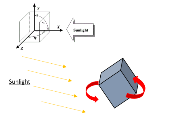
The maximum value of power is obtained for three sides under sunlight with ϕ = 45° and v = 55°
Solar Cells are connected in series but every section will be in parallel: every solar panels will be connected to each other in parallel.
PCC
A MPPT is used to obtain the better power as possible. The Solar Panels will deliver a voltage until 4V. So, the MPPT have to handle a maximum input voltage of 4V and deliver a voltage of maximum 3.7V. Regulators are used to provide the different parts of CubeSat with 3.3V and 5V.
A microcontroller has to control the energy distribution in the entire CubeSat. So, it needs four digital/analog outputs to the other modules and two to the battery: One connection to provide the microcontroller and an other to send the step of charge. An UART communication is used between the EPS and the OBC. An SPI communication is used for the other connections.
Files
Feasibility Study EPS
The feasibility study aims to assess the practicality of the EPS module. The purpose of this stage is to assess the performance according to the association of the requirements and the state of the art.
PCC
As a brief remind, the PCC module is responsible for the distribution and regulation of electricity through the CubeSat. There is many requirements to fit such as the protection of the modules, the communication with the OBC and the energy distribution from PV cells to battery for the storage and/or to module for the consumption.
The MPPT will have to handle a maximum input voltage of 4V from solar panels and supply power to a 3.7 V battery. Redirecting the current to regulators providing energy to the modules (3.3V and 5V). The modules are both connected to the panels and the battery, that is why regulators will be connected in parallel to the MPPT output and the battery. An additional cell has been integrated because of the large amount of energy needed for the detumbling phase, the battery will not be enough to ensure the power supply in this time.
It has been established that a 3.3V regulated bus detumbling could be used to supply ADCS and OBC (which are on the same board), the other 5V converters will be connected to TCS and EDT. These figures are for now only indicative and will have to be changed according to the needs of each module.
The MCU is used for gathering and computing the housekeeping data, taking decisions for connecting/disconnecting users in case of failure and communicating with OBC thanks to an UART bus. The battery level of charge is harvested through an analog-digital converter.
A schematic of the description above, develops the architecture more clearly:
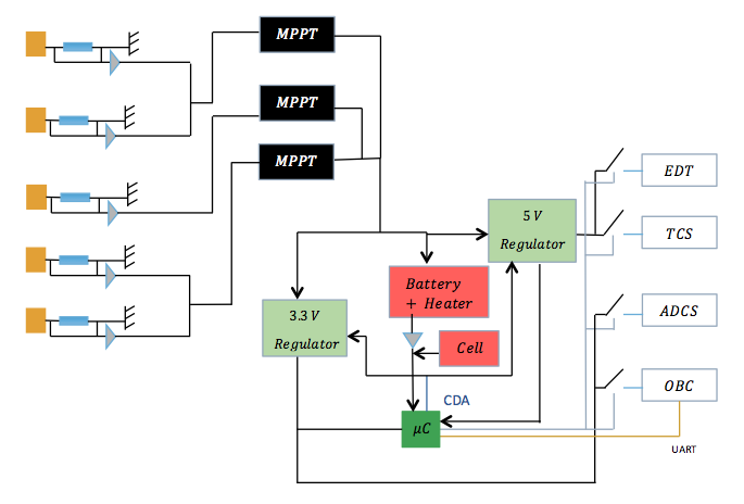
According to the availability on the market, the type of regulators varies as a function of the input and the output. As the battery charge regulator receives a various input from MPPT which can be superior or inferior to 3.7V, it has to work as a step-up and step-down regulator. For increasing the voltage from 3.7V to 5V the second regulator should be a step-up. As the last regulator decreases the voltage to 3.3V, it should be a step-down regulator. But, since the battery’s output voltage decrease with its level of charge, the input voltage of regulators could be under 3.3V. Therefore, the last regulator should not be only a step-down regulator, it has to be a step-up/step-down voltage regulator, with a 3.3V output.
Microcontroller
The microcontroller has to handle the energy distribution of the entire CubeSat, and has to communicate with the OBC too. Thus, it needs four digital/analog outputs (EDT, ADCS, Telecom, OBC), one BUS with a two-way communication between the microcontroller and the OBC in: UART. And two inputs with a power BUS and one another BUS which is used to send data of the battery level of charge to the microcontroller: SPI.
Energy consumption
Generally, microcontrollers consume few energy, around the mirco ampere for the “Active mode” and around the hundreds of nano ampere for the “Off mode”. Others microcontrollers are more economical, they can be used with six different ways.
Voltage range
The voltage range of the microcontroller depends of the output voltage of the battery, which is 3.7V.
Almost microcontrollers have a voltage range of 2-3.6V, except for the ATMEGA1281 which has a voltage range of 2.7-5.5V.
Memory
In the light of the functions of the microcontrollers the memory didn’t have to be huge. All the microcontrollers are viable.
PV
The sizing of this module has to be accurate and margins have to be considered to be sure of the capability of production compare to the consumption.
The energy production of the PV mainly depends of two factors which are the efficiency and the surface area of the cells. Other characteristics such as temperature, way to wire or weight have to be taken into account.
Temperature
The PVs are subject to high electro magnetic radiation that cause huge variation of the temperature over time. (Around 100°C of difference between solar exposition phasis and eclipse). Then PVs shall be sized to undergo the extreme conditions of space environment.
Surface & Efficiency
The limited surface area on each side of the nanosatellite implies some restriction on the type of PVs available on the market and in compliance with the need of production. Efficiency and surface being related to each other, finding a compromise between them could imply an increase in the cost.
As panel’s efficiency decreases over time, the capacity of production shall be computed for the beginning and the end of life. According to the allocated power budget, efficiency shall be maximized, Triple Junction solar cells are well indicated for this last condition. Generally, the solar cells designed for 1U CubeSat are between 25% and 30%.
Triple junction solar cells are used in space, our CubeSat will integrate this technology too. To save money, a choice of solar cells rather than complete solar panel has been studied.
The advantages of this solution are the flexibility on architecture, the cheaper cost, and the number of choices between different TJ solar cells
The disadvantages of this solution are that the architecture is more complicate than solar panels’s architecture (due to the big number of solar cells), the sensors, wire and magnetorquers have to be add by ourselves (inducing more risks on the result), and some solar cells such as TASC cells have not coverglass on it. In this case, there is a need to add encapsulation on cells aftermarket coverglass.
tTherefore, the first option will be considered as our solution if the budget enables it. Otherwise, the second option will be considered even if it induce an increase of risk of mission failure.
PV Feasibility Study Download
You can find below the study of two kind of PVs Ultra Triple Junction Solar cell from Spectrolab, and ISIS TJ 3G30A
The results calculated are the power generated by only one face of the CubeSat. However the CubeSat has 5 sides with solar panels and between one and three sides can be under Sunlight at the same time. The number of sides which receives solar power is related to the orientation of the CubeSat. To estimate the power generated by the entire CubeSat, the calculations have to take in account the inclination of the satellite, in other words, the angles (here in spherical coordinates).
Battery
To supply the modules in energy, at least one rechargeable battery is needed. There are different types of batteries (Typically Li-Ion and NIMH). The technology, the attitude in a cold and hostile environment and the power consumption have to be considered to size the battery module.
Since the CubeSats have already a huge rate of failure (due to the hostile environment that they have to face with), the battery considered in the ECE³SAT has to be as safe as possible technology designed for space.
Energy needed
There is not a Power Budget for the ECE CubeSat, therefore an average of the precedent CubeSat is used:
For improving the battery lifespan, it has to be neither fully charged nor depth discharged. Precisely, the level of charge needs to be maintained between 20% and 90% of the total capacity. According to the amount of energy needed by the system, this should represent 70% of the battery capacity. Then, in consequence the battery should deliver 3.21 Wh.
Energy used
To improve the lifespan of the battery, it has to be neither fully charged nor depth discharged. The level of charge needs to be maintained between 20% and 90% of the total capacity.
Moreover, in average, 2.25Wh will be needed during an eclipse according to the power budget part.
Thus, a battery will be required with 3.21Wh, or a capacity of 0.87 Ah with a voltage of 3.7 V.
It is in adequacy with the 1 Ah generally used.
The CubeSat may also consider the use of a non rechargeable battery to execute one time operation. It could be very interesting for some specific operations such as in the detumbling mode in the ECE³Sat case. So, it would a primary battery of 1Wh.
Vacuum
At low earth orbit, the atmosphere influence at really low level the space environment. Therefore, LEO is considered to be in vacuum conditions.
The battery designed for the CubeSat has to be able to charge and to furnish electricity to modules in these vacuum conditions.
Temperature
The temperature in space is very low and it is important to take into account during the design of the modules. The battery is always confronted to the natural discharge issue, but in a cold environment this problem increases. That means that the battery has to be designed for space, and has to resist to low temperature.
The natural discharge of the battery has to be considered according to this extreme temperature. The battery should be able to work well and without too much loss for a temperature of 0 C°. This aims to improve the charge of battery and avoid the depth of discharge.
Models EPS
To validate the theory, we made some tests with the same type of components than in our achitecture.
The main purpose of this realization is to study the physical feasibility of the circuit builded with ISIS. For ensuring precise and reliable results we simplified a lot the scheme by using only one PV associated with one MPPT at first. In this way, the energy generated will charge a 3.7V battery and shall be able to redistribute it into connectors linked with regulated switch.
To do so, we used:
- CIGS flexible solar cells
- STEVAL ISV006V2 board with a MPPT SPV 1040 and potentiometers
- 3.3V Step-Up/Step-down Voltage Regulator
- 5V Step-Up Voltage Regulator
- Li-Po Battery 3.7V
Solar cells efficiency
First of all, we have to check the efficiency of the CIGS solar cells. To do so, we used a luxmeter, a multimeter and a load.
CIGS cell is 24 cm by 7.3 cm
The solar power is of 1W/m² according to the lux meter.
The voltage at the output of the solar cell is of 10V for a 0.2A current.Then, the cells have a output Power of

We can deduce the efficiency of the cell

Voltage regulators test
We check the voltage regulation through Voltage 3.3V regulator and Voltage 5V regulator using both battery or solar cells. The output voltage of regulators can be regulated only if the current through it is strong enough to manage the voltage. Therefore, for a bad sunlight (such as under a 1W light), the regulator cannot works. At the opposite, it works under the real Sunlight, outside during the day. Therefore the regulators should also work in space. You can find the description of the test in the document at the end of the page: Model EPS.
MPPT Board
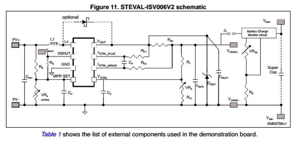
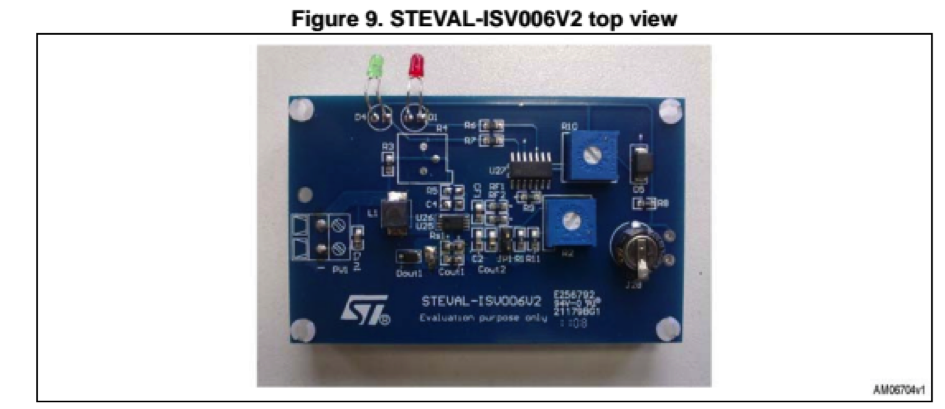
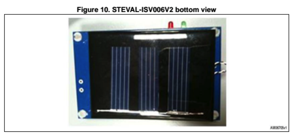
First Stage: STEVAL-ISV006V2
This device gather both PV (220 mW) and MPPT (SPV1040) on the same board. You can find below the scheme of the circuit and the top and bottom view:
We added a connector on the PV input pin for a better handling during the measurements.
The user can directly act on the circuit by the intermediary of a jumper and 3 potentiometers (VR4, VR2, VR10)
tAs you can see a jumper named J1 linked a second stage which allows the battery to be charged or not (the battery can be simulated by the on-board super capacitor). The jumper allows to discharge manually the battery or inhibit the charge when PV is illuminated.
Moreover both pins of J1 will be interesting points to take current and voltage samples on the MPPT (SPC1040) output or battery output. The device input corresponds to the PV pins.
- VR4 (0-1 kΩ)
This variable resistor regulates the input voltage of MPP-SET
(SPV1040 pin). The SPV1040 device is a low power, low voltage,
monolithic step-up converter with an input voltage range from 0.3V
to 5.5 V, capable of maximizing the energy generated by a single
solar cell. The PV shall be illuminated as it generates enough input
voltage to turn on the MPPT (MPP-SET shall see 0.3 V at minimum).
When VR4 equals to zeo, MPP-SET is directly connected to the ground.
After measuring the input voltage, VR4 can be estimated thanks to
the following voltage divider equation:
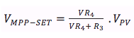
Equation VMPP-SET - VR2 (0-1 MΩ) This variable resistor controls the desired ouptu voltage by regulating the voltage of the pin Vctrl. The algorithm inside the MPPT will compute the maximum power point according to this value. With the aid of a multimeter connected to the good pin of the jumper, we can display the MPPT output voltage. The resistor shall be configured until the desired ouput is obtained.
- VR10 (0-1 MΩ) This resistor is connected to the charge regulator and regulate the amplification of the input signal.