TCS: Telecommunication System
Telecommunication System (TCS)
Presentation
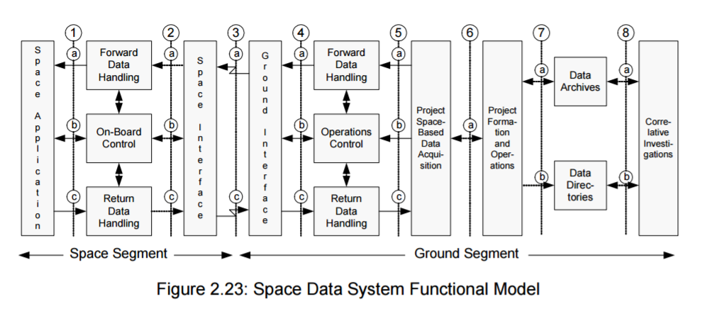
The TCS, or telecommunication system, communicates with the Ground Control Station. It sends data to the Earth and receive orders (to shut down the satellite because of an external factor for example). The data sent to the Ground Control Station are transmitted to the TCS by the OBC. And, in the same way, orders sent from Earth to TCS are transmit to the OBC.
Subsystem division
The TCS is divided in three subsystems which are Antenna, Modulation/Demodulation (MODEM) and Data processing.
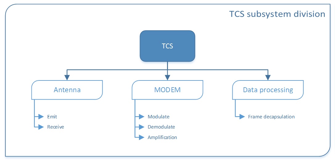
The first subsystem, is mixed of two antenna embedded on the CubeSat. One to receive order, and the other one to send data and transmit messages.
The MODEM convert signals received and sent by and from antenna. It apply a digital-to-analog conversion for the orders received, and analog-to-digital conversion for the data which has to be send. The signal is amplified since there is attenuation of the signal during the transmission process.
The third subsystem, data processing, is the encapsulation and decapsulation of the frame. It corresponds to the encryption of the frame before being sent.
State Of The Art TCS
Anthena
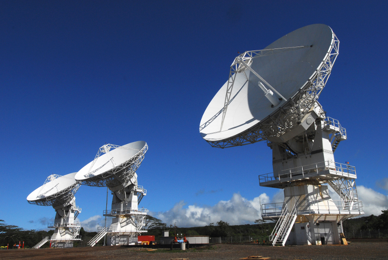
The role of the antenna of CubeSat is to create the electromagnetic waves which contain the necessary information for the realization of the spatial mission to be able to receive them and interpret them on the ground. The system converts the existing electric signal containing the information in electromagnetic signal in the space.
Protocol
The communication subsystem of a CubeSat has two main purposes:
- Transmit telemetry data, including a beacon.
- Provide a mean for the satellite to communicate with ground station and vice versa. (The Ground station will receive data from the CubeSat only in this direction)
The protocol for communication follow the layer Model :
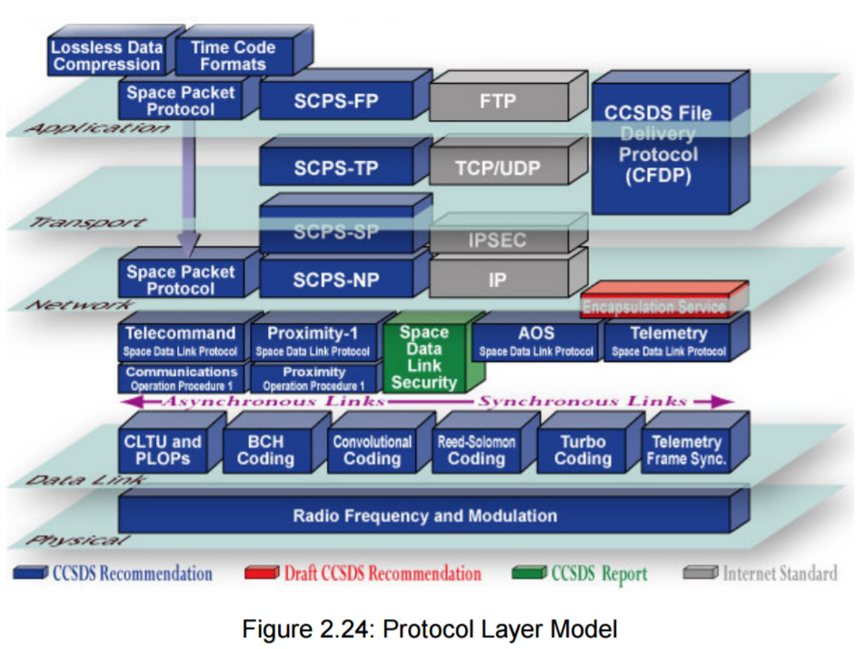
Several protocol can be used for satellites. The most used are the following :
- AX.25 :
- It is the most used data link layer protocol between radio amateurs is AX.25
- CCSDS :
- It is the most used transmission protocol for professional satellite
The carrier is a pure sinusoidal signal of constant amplitude, frequency and phase. This carrier must be modified to carry the signal we want to transmit. We say that the signal is modulated.
The carrier is described by the equation y = a sin (2πFt + φ) in which:
a is the amplitude of the carrier,
F is the frequency of the carrier,
φ is the phase of the carrier.
To modulate the carrier, we will modify one of these three parameter as function of the signal to transmit.
Concept of envelope: The envelope of a signal is the external form of the modulated signal.
Baud rate: The baud expresses the number of modulation moments per second, this is the modulation rate. Each modulation moment being able to transmit one or more bits.
Connection flow: Produces the baud rate and the length of the symbol in bit.
Spectral efficiency: Ratio between flow rate (kb/s) and bandwidth (Hz)
Concept of symbol: Unit of information transmitted by moment of modulation. A symbol is a certain combined state of frequency, amplitude and/or phase that represents a number of bits. If a symbol represents one bit, it is the binary case. The single bit (k=1) can either be a logical 1 or 0, thus rendering two symbol possibilities (M=2). If a symbol consists of two bits (k=2), there is a total number of four symbols (00, 01, 10 and 11), therefore M=4. The relationship between the number of symbols and bits is:
M = 2k
Nyquist’s theorem gives the upper limit of the bit rate for a system defined by the following equation:
C = 2 B log2(2k)
C = 2 B log2(M)
C is the channel capacity in bps
B is the channel bandwidth in Hz
Sizing TCS
The different studies we did are referenced there :
Electronic Components
General constraints :
Altitude: 400 – 1000 km above the sea level
Inclination: 0° to 56° (inclination of ISS)
Radiation: resisting UV radiation, X, protons, and plasma in LEO
Duration of lifetime: 2 weeks to 1,5 month
Vibration on the launch
Maximum consumption of the CubeSat communication sub-system is 1,5W.
To respect those values, we saw the cards on board of other cubeSats. The band chosen for downlink communications is 435-438 MHzand the transmission rate: 1200 to 9600 bauds
Mecanical Components
Environmental constraints :
- Thermal constraint: -150°C to +150°C
Radiation constraint: resisting UV radiation, X, protons, and plasma in LEO
The friction on the external surfaces including the antenna shall not impact its functioning
The erosion due to the Oxygen (200-100km) must be managed
The luminescence due to the Oxygen (200-100km) must be managed
Launch vibrations
Compatibility criteria :
Transmission rate: 1200 to 9600 bauds
Broadcast max power: 1,5W
Frequency band: 435 to 438 MHz
Antenna gain max: 0 to2 dB
Dipole length: λ/4 minimum, λ/2 required
Interface: I²C
Envelope stowed: 98 mm x 98 mm x 7 mm
for the choice of the antenna, two companies designing parts for CubeSats could propose interesting solutions for our project: ISIS and Clyde Space, both proposing systems of antennas. Our choice is towards a solution similar to the ISIS dipole antenna because characteristics match with system and environmental specifications:
low gain: 0bB in UHF
<2W
1200 - 9600 bauds - <100g
almost omnidirectional
Dipole length: λ/2
Orbit and data estimation
The orbit period of the ECE3SAT is between 90 and 105 min. It’s about 15 revolutions around Earth per day. We have only 3 orbits of 7 to 13 minutes per day that we can truly be exploited. That is aproximatly 30 minutes of visibility per day.
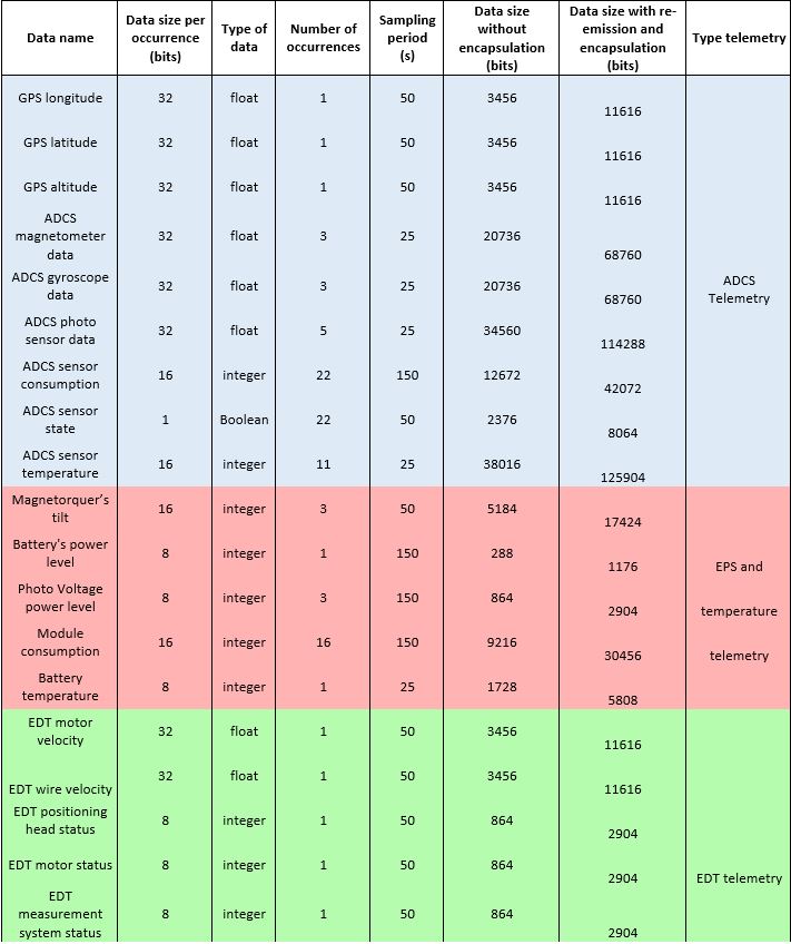
Note : The period of sampling is arbitrarily fixed here.
For the moment the total amount we have to transmit per orbit is 207663 bits or about 208 kbit.
We must also assure that we can stock the equivalent of 8 orbits of data in the memory of the satellite: we are not able to transmit data each orbit of our satellite and sometimes, you can have 8 successive orbits without visibility as we can see in Gpredict for similar projects.
Thermal simulation TCS
We can identify four sources of heat:
Equipment: The components within the satellite produce heat with the energy they consume.
Solar radiation: This is the most important source of heat. The solar flux accounts between 1353 and 1375 Watts / m².
Albedo: This refers to the solar radiation reflected by the Earth. This energy represents an average radiance of 196 W / m² in the sunny hemisphere of the Earth.
Earth radiation: This accounts an energy of 190W / m² up to 240W / m².
The data coming from the FUNcube-1 also gave us the temperature range in which a satellite operates : from -30 ° C to 85 ° C
Model TCS
The purpose of this technical realization was to validate data exchange with system specifications. To do so we decided to build our own anthena.
That’s why we used a communication card provided by the AMSAT-F, a DVB-T dongle, an LNA amplifier and our home-made antenna.
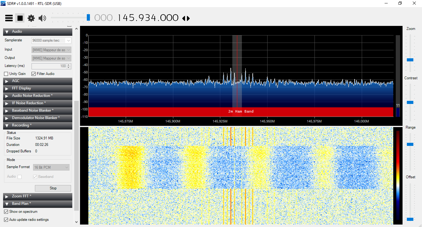
Software Defined Radio (SDR)
For the software part we used the software SDRSharp, a software that allows us to pilot the key via an interface of spectrum analysis and selection of frequency, bandwidth and signal processing tools.
Doppler effect
In parallel with the SDR we used the software Orbitron to have a satellite tracking station with TLE (Two-Line Elements) information and automatic correction of the retroactive Doppler effect on SDRSharp.
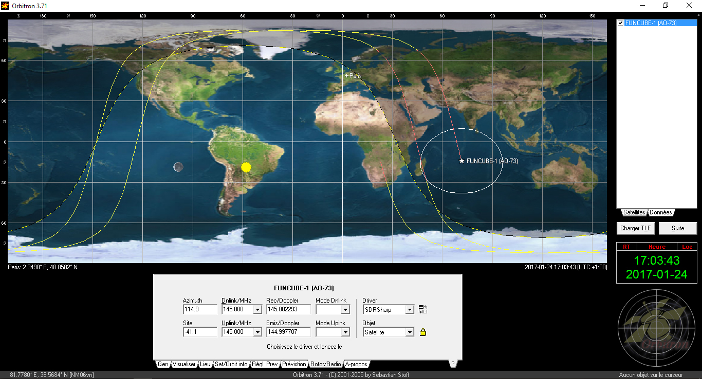
The two-line orbital parameters (TLE) are elements measured and calculated by NORAD and NASA, not only for artificial satellites, but also for space debris. They allow Orbitron to calculate the position of objects in orbit at any time because they follow the laws of Kepler and Newton.
By setting the input text files of the software, we can easily isolate the satellites we are interested in, namely the CubeSat of the AMSAT.
Once selected, we have access to a lot of satellite information, including emission frequency and Doppler calculation.
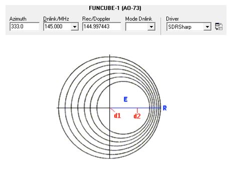
The Orbitron software allows us to control the frequency selection of SDRSharp by taking into account the value of the Doppler in real time.
Demodulation
For the demodulation, we had several choices :
The first option is that we can either use an open source amateur radio software: MULTIPSK. This one allows us to demodulate the signal modulated in BPSK in real time. To send the stream from SDRSharp to MULTIPSK, we have installed Virtual Audio Cable which allows to direct the output of SDR to the input of the demodulator.
The second option is to use a more specific software that only works with the FUNcube and its associated dongle. This is the FUNcube Dashboard software which is dedicated to the telemetry of this CubeSat. The software’s interface is a high level of programming: We can’t see any treatment of data and that we access directly to the data of telemetries interpreted in background by the dashboard. In the same way, the software is provided with the virtual audio gateway as input and the software identifies and interprets in real time the signal which must be at 1200 bauds in BPSK modulation. From the moment this software recognizes an AX-25 frame, it translates it into telemetry data.
Dongle
We decided to use the following TNT USB key:
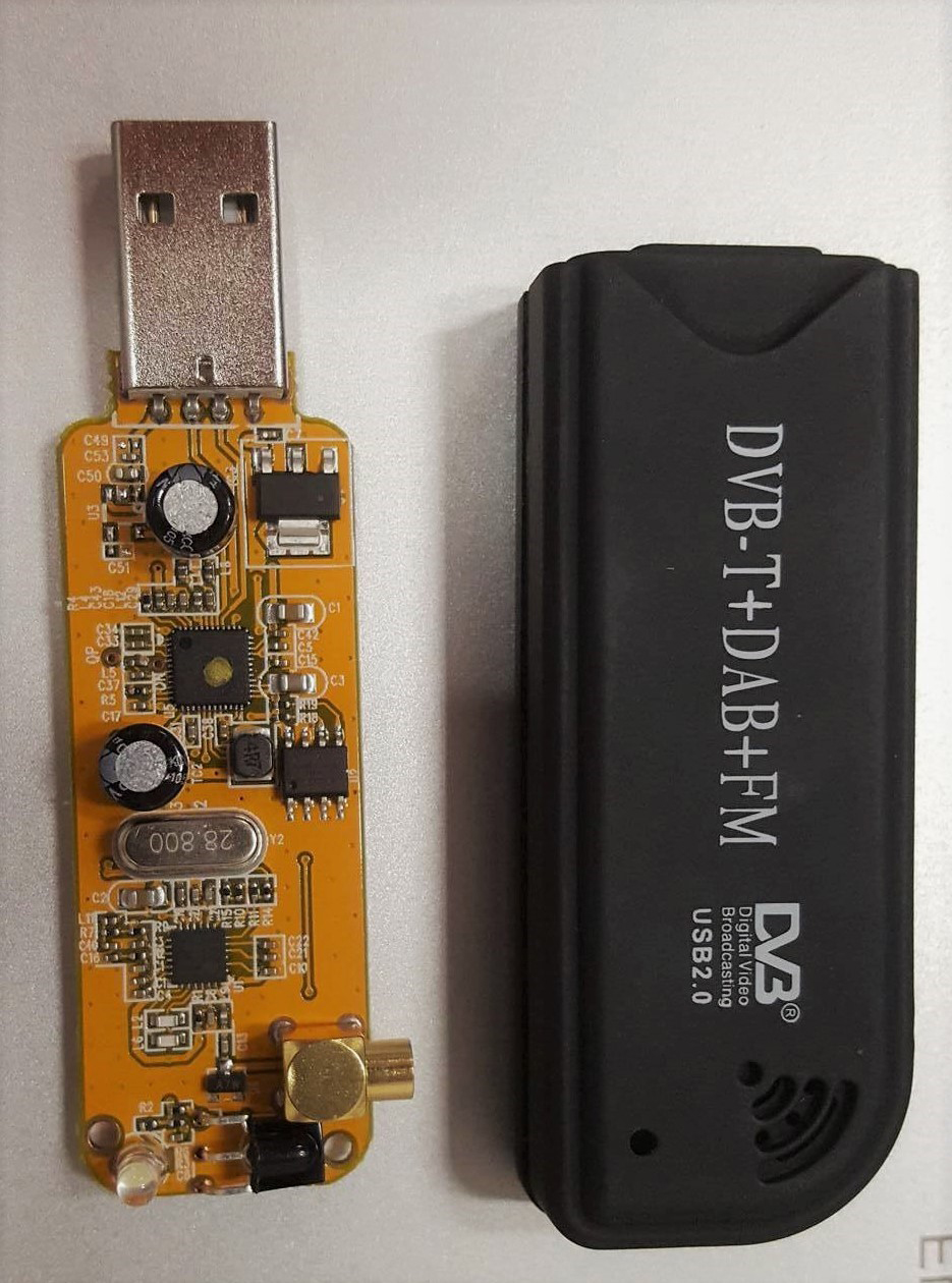
This key contains the RLT2832U chip and the R820T2 tuner. It competes perfectly with the usual scanners since it covers from 30MHz to 1500MHz, and this with two spectrum analyzers:
A 2D: frequency / amplitude
A 3D: “waterfall” frequency / amplitude / time
The disadvantage of this USB kit is that the antenna supplied with it is not suitable for the use we want to make of it. To overcome this problem, we started the realization of an antenna optimized for our study
Anthena realization
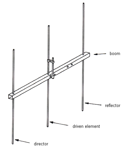
We were targeting the frequency of the FUNcube in telemetry which is 145.935MHz. This is why we decided to manufacture an antenna called Yagi-Uda 3 elements.
The Yagi-Uda is a type of antenna that has an active element, the dipole, which will be fed with high-frequency signals. In front of the dipole takes place a slightly shorter element, this element is called “director”. Behind the dipole is positioned a slightly longer element called “reflector”.
We made this antenna with a square aluminum profile and 8 mm aluminum rod.
Concerning the length of the dipoles, it was chosen according to the frequency of emission of the FUNcube:
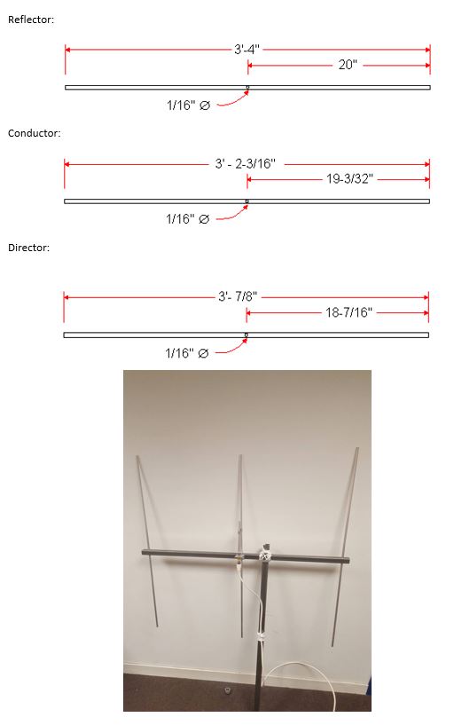
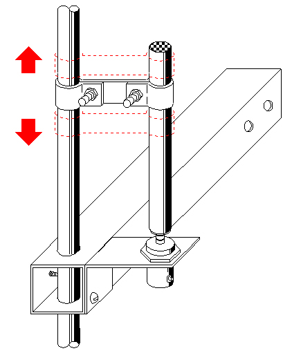
To tune the antenna impedance, we installed a gamma match element as follows:
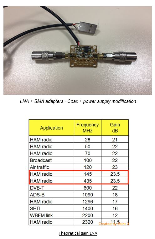
Preamplifier
The chosen preamplifier is the LNA4ALL, a preamplifier and a low-pass filter (LNA), with SMA Female connectors, for VHF and UHF frequencies covering all bands from 28 MHz to 2500 MHz (2.5Ghz). We chose this one because it allows to improve very clearly the reception performance, on all bands VHF and UHF up to 2.5Ghz, of a TNT key RTL-SDR.
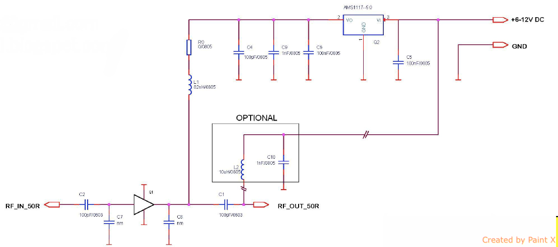
The LNA was then bought and the model assembled.